Need round aluminum components with specific features, but worried about achieving the required precision? I know finding suppliers who can consistently deliver high-quality turned parts can be difficult.
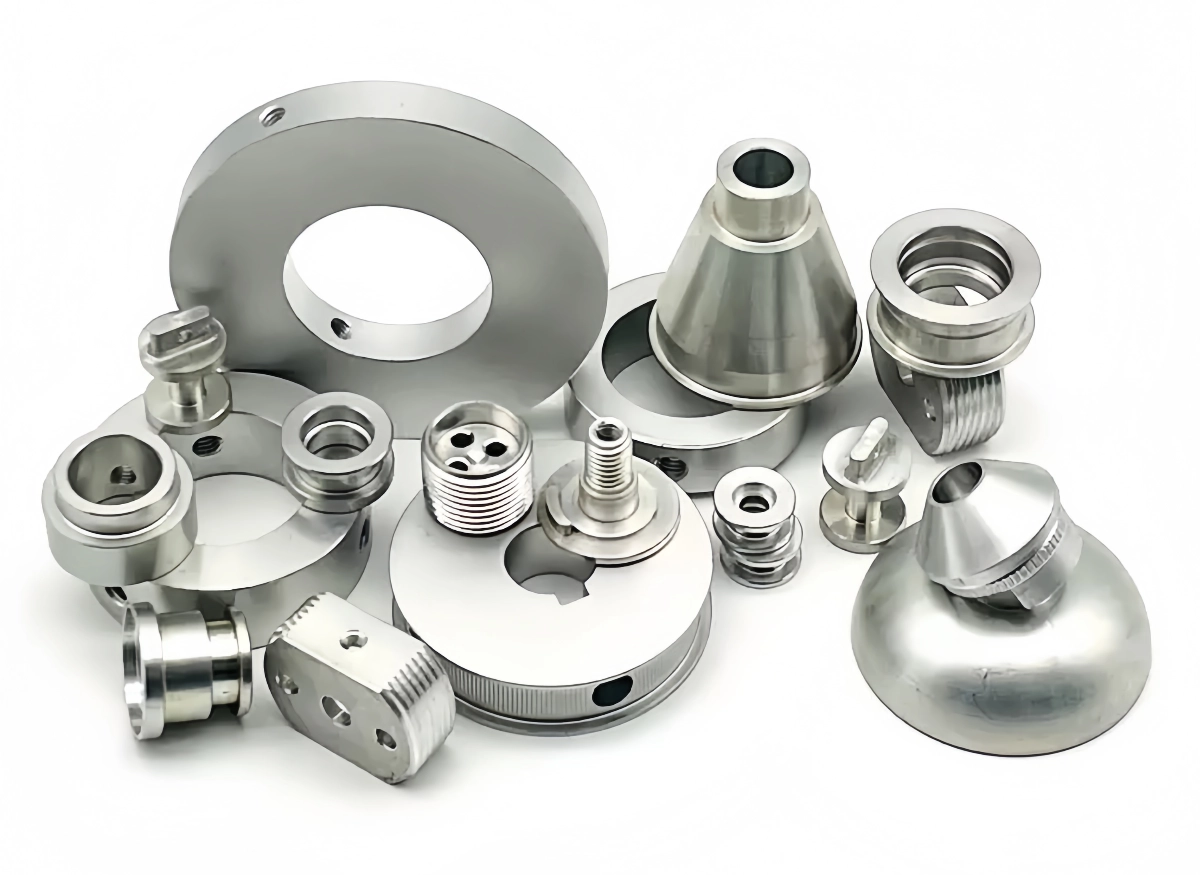
From my background in manufacturing, aluminum turned parts are components shaped by rotating aluminum stock (rod or bar) against stationary cutting tools on a lathe. I rely on CNC lathes to produce these parts with excellent accuracy and surface finish.
This process is ideal for creating cylindrical or round features. But what constitutes a high-quality turned part? How exactly does a lathe create these shapes? How intricate can these parts get, and how is their quality ensured throughout production? Let’s explore these aspects.
What defines high-quality aluminum turned parts?
Many machine shops offer turning services. How can you tell if the aluminum turned parts you receive will truly meet high standards, beyond just basic shape?
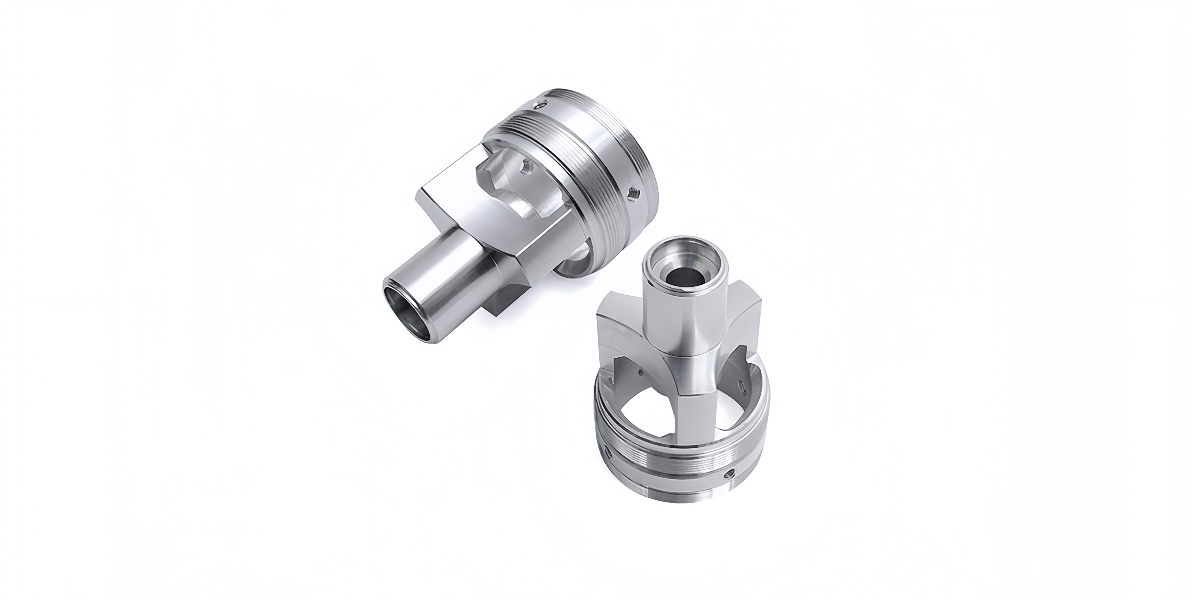
In my experience, high-quality aluminum turned parts are defined by their strict adherence to dimensional tolerances, excellent surface finish, precise feature formation (like grooves or threads), lack of machining defects, and consistent quality from the first piece to the last.
Achieving high quality in aluminum turned parts involves more than just spinning metal on a lathe. It requires a combination of precise machinery, skilled operation, appropriate material selection, and rigorous quality control. Key characteristics define a truly high-quality turned component:
Dimensional Accuracy and Tight Tolerances
Meeting Specifications: The part must conform precisely to the dimensions specified on the engineering drawing. This includes diameters (outside and inside), lengths, shoulder locations, groove depths/widths, and thread specifications.
Concentricity and Runout: For parts with multiple diameters or features along the axis, maintaining concentricity (features sharing the same center axis) and minimizing runout (wobble as the part rotates) is crucial for quality. This requires accurate machine setup and chucking/collecting.
Form Tolerances: Features like cylindricity (how close to a perfect cylinder diameter is) and roundness must meet the drawing requirements.
Superior Surface Finish
Smoothness (Low Ra): Turning can produce very smooth surface finishes on aluminum, often measured by Ra (Roughness average). Quality parts have a finish appropriate for their application (e.g., smoother for sealing surfaces or aesthetic parts) and free from excessive tool marks.
Consistency: The finish should be uniform across the specified machined surfaces.
Absence of Defects: Free from chatter marks (vibrations during cutting), feed lines that are too coarse, scratches, or tool drag marks.
Precise Feature Formation
Sharp Details: Grooves, chamfers, radii, and threads should be cleanly cut with sharp, well-defined edges according to the drawing.
Accurate Threads: Both internal and external threads must meet specifications for pitch, form, and class of fit.
Material Integrity
Correct Alloy and Temper: Made from the specified aluminum grade, ensuring the final part has the required mechanical and physical properties.
No Machining-Induced Stress/Damage: Free from burns, excessive work hardening in localized areas, or surface defects caused by dull tooling or improper cutting parameters.
Consistency
Part-to-Part Repeatability: In a production run, each part should be virtually identical to the others within the specified tolerance band. This is a key benefit of CNC turning.
This table summarizes key quality attributes for turned components:
Quality Attribute
Defining Characteristic
Importance
Dimensional Accuracy
Meets all drawing dimensions and tolerances (diameter, length)
Ensures proper fit, function, interchangeability
Geometric Accuracy
Good concentricity, runout, roundness, cylindricity
Critical for rotating parts, sealing, alignment
Surface Finish
Smooth (appropriate Ra), uniform, no chatter/scratches
Affects appearance, wear, sealing, fatigue life
Feature Definition
Clean grooves, threads, chamfers matching specs
Ensures functional performance of features
Material Integrity
Correct alloy/temper, no machining defects
Guarantees expected mechanical properties
Consistency
High repeatability between parts in a batch
Ensures reliable assembly and performance
A focus on all these areas distinguishes a provider capable of delivering truly high-quality aluminum turned parts.
How are aluminum turned parts made on lathes?
Turning seems basic – spinning metal and cutting it. But how does a modern lathe actually create precise aluminum turned parts with complex features?
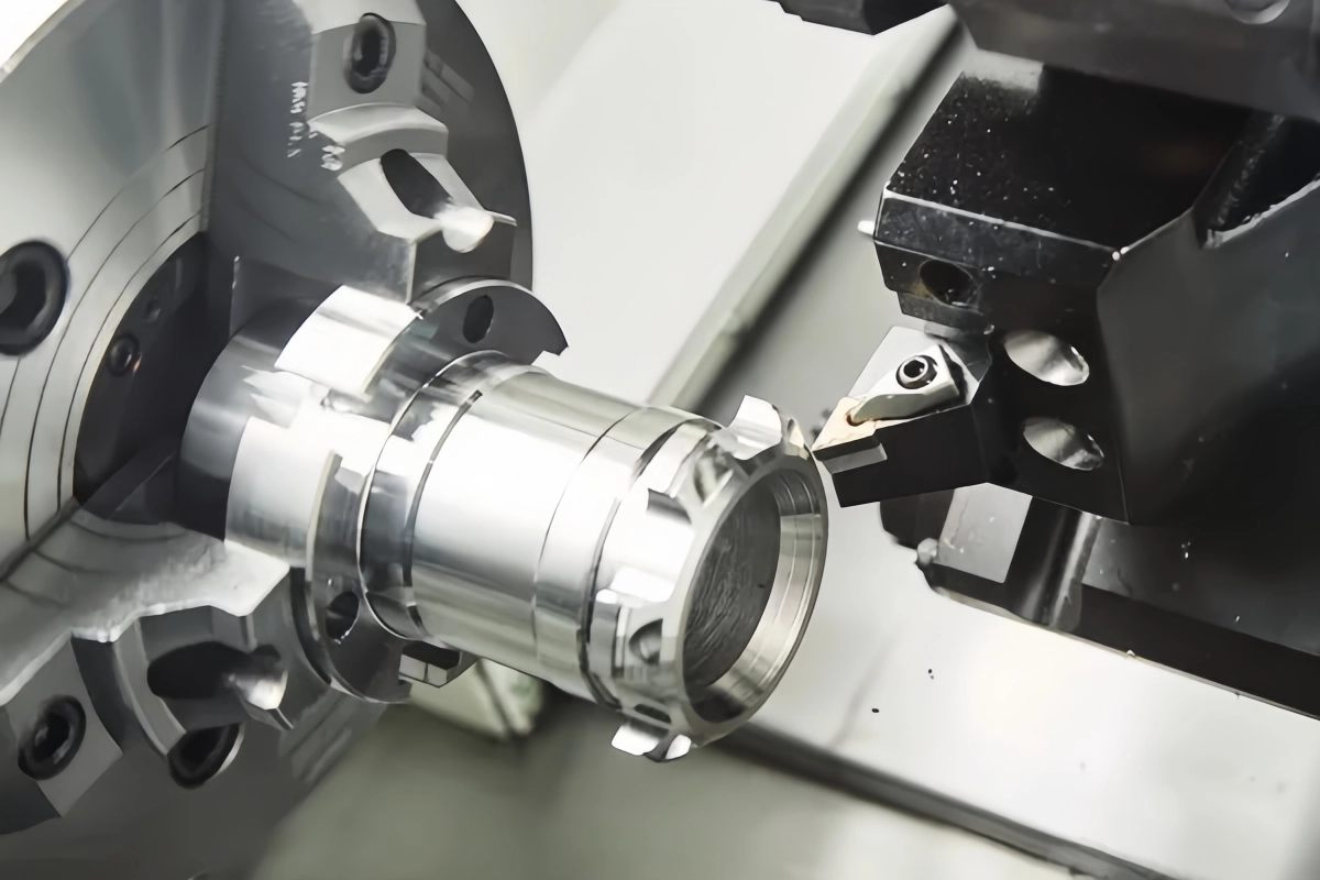
As a manufacturer using this technology, we make aluminum turned parts by securely rotating aluminum bar stock at high speed in a CNC lathe. Precisely controlled cutting tools then move along and across the rotating stock to remove material and generate the desired cylindrical shapes and features.
The creation of aluminum turned parts relies on the process of turning, performed on a machine tool called a lathe. Modern manufacturing predominantly uses CNC (Computer Numerical Control) lathes for precision, repeatability, and efficiency. The fundamental principle involves rotating the workpiece (aluminum rod or bar stock) while a stationary or moving cutting tool removes material.
The CNC Turning Process Steps:
Workpiece Preparation and Loading:
Raw material, typically round aluminum bar stock of a suitable diameter and alloy, is cut to a manageable length.
This stock is securely mounted in the lathe’s spindle, which provides the rotation. Common methods include:
Chucks: 3-jaw or 4-jaw chucks grip the outside diameter (for larger stock or irregular shapes).
Collets: Precision sleeves that grip the outside diameter very accurately, often used for smaller diameter stock and high precision or high-volume production. Provide excellent concentricity.
Bar Feeders: For automated production, long bars are automatically fed through the spindle and gripped by a collet after each part is finished and cut off.
Tool Setup:
Various cutting tools (inserts made of carbide or other hard materials held in tool holders) are mounted onto the lathe’s turret. The turret is an indexable tool holder that can quickly rotate different tools into the cutting position as needed by the program.
Tools include those for turning outer diameters, facing ends, grooving, threading, drilling center holes, and boring internal diameters.
The precise position of each tool tip is measured and input into the CNC controller (tool offsetting).
CNC Programming (CAD/CAM):
Similar to milling, the process starts with a CAD model or drawing.
CAM software is used to plan the sequence of operations and generate the toolpaths. The programmer selects tools, defines cutting speeds (based on surface feet per minute or meters per minute for the given diameter and material), feed rates (how fast the tool moves along the workpiece), and depths of cut.
The software generates the G-code program that will direct the lathe’s movements.
Machining Operations:
The spindle rotates the aluminum stock at the programmed speed (RPM).
The CNC controller executes the G-code, moving the turret and selected cutting tools along precise paths relative to the rotating workpiece. Common operations include:
Facing: Cutting the end of the bar flat and perpendicular to the axis.
Turning (OD): Moving a tool along the length to reduce the outside diameter. Creates cylindrical or tapered shapes.
Grooving/Parting: Plunging a specifically shaped tool into the workpiece to create grooves or cut the finished part off the bar stock (parting off).
Drilling: Using a drill bit mounted on the turret (or a tailstock) to create a hole along the center axis.
Boring (ID): Using a boring bar to enlarge and true an existing hole or create precise internal diameters and features.
Threading: Using a specialized tool to cut internal or external threads.
Coolant is continuously applied to lubricate, cool the cutting zone, and wash away chips.
Part Completion and Quality Check:
Once all operations are complete, the finished part might be parted off the bar stock.
The part is cleaned and inspected to ensure it meets dimensional and finish specifications.
This table shows common turning operations:
Operation
Tool Movement
Workpiece Rotation
Resulting Feature
Facing
Tool moves across end
Yes
Flat end surface
Turning (OD)
Tool moves along axis
Yes
Reduced diameter, cylinder, taper
Drilling
Tool moves into axis
Yes
Center hole
Boring (ID)
Tool moves along axis (inside hole)
Yes
Enlarged/precise internal diameter
Grooving
Tool plunges radially
Yes
Circumferential groove
Threading
Tool moves along axis (synchronized)
Yes
External or internal threads
Parting Off
Tool plunges radially
Yes
Separates part from stock
Modern CNC lathes, especially multi-axis and mill-turn centers, allow for highly complex aluminum turned parts to be produced efficiently and accurately.
How complex can custom aluminum turned parts be?
I need a round part, but it has some non-cylindrical features like flats or off-center holes. Can turning handle this, or how complex can these parts actually get?
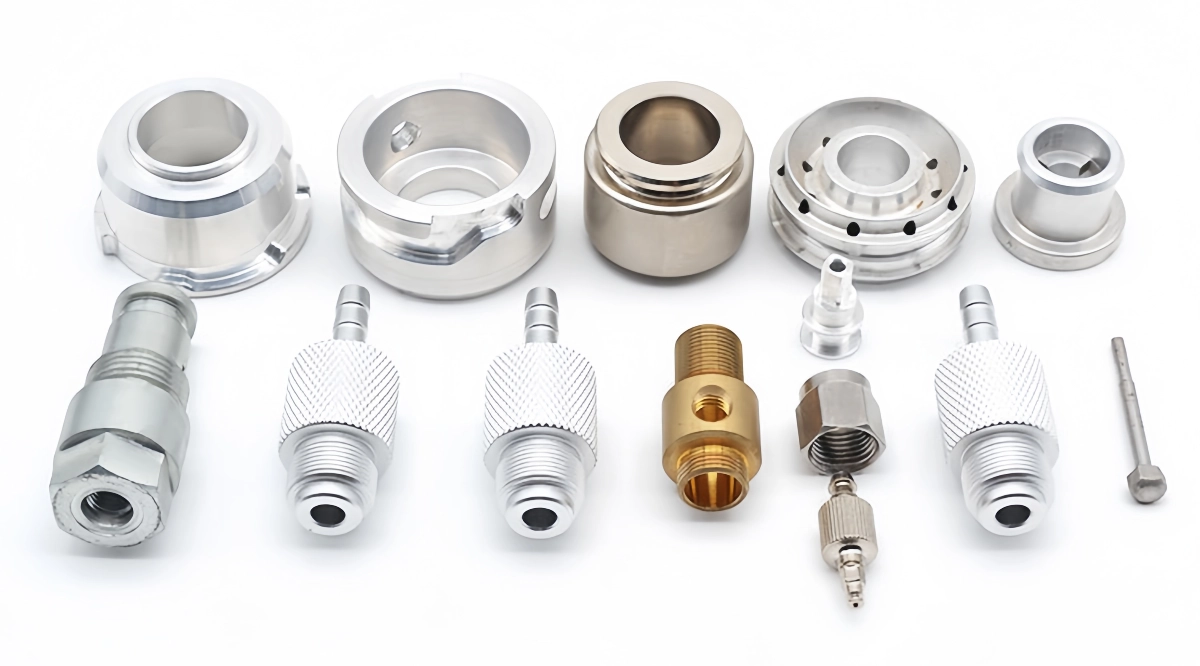
While basic turning creates cylindrical shapes, modern CNC lathes, especially mill-turn centers, allow for significant complexity in aluminum turned parts. We can produce parts with multiple diameters, tapers, threads, and grooves, and even incorporate milled features like flats or cross-holes in one setup.
The complexity achievable in custom aluminum turned parts has evolved significantly with advancements in CNC lathe technology. While traditional turning primarily produces parts with features concentric to the main axis of rotation, modern machines offer much greater capabilities.
Basic Turning Complexity:
Standard 2-axis CNC lathes (controlling tool movement along the Z-axis length and X-axis diameter) can easily produce parts with:
Multiple Outside Diameters (ODs): Stepped shafts, parts with varying cylindrical sections.
Multiple Inside Diameters (IDs): Achieved through drilling and boring operations.
Faces and Shoulders: Flat surfaces perpendicular to the axis of rotation.
Tapers: Conical sections (both external and internal).
Radii and Chamfers: Rounded or angled edges between features.
Circumferential Grooves: O-ring grooves, snap ring grooves, decorative grooves.
External and Internal Threads: Standard or custom thread profiles cut along the axis.
Advanced Complexity with Multi-Axis and Mill-Turn Centers:
The real leap in complexity comes with more advanced machines:
Live Tooling / C-Axis: Lathes equipped with live tooling have rotating tools (like end mills or drills) mounted on the turret, in addition to the standard stationary turning tools. The lathe spindle can also be precisely indexed or rotated (C-axis control). This allows for:
Cross-Drilling: Drilling holes perpendicular to the main axis.
Cross-Tapping: Tapping threads into cross-drilled holes.
Milling Flats: Creating flat surfaces on the outside diameter.
Milling Slots or Keyways: Cutting slots along the length or circumference.
Y-Axis: Adding a Y-axis (tool movement perpendicular to both X and Z axes) further enhances capability, allowing for off-center drilling, milling complex profiles on the face or diameter, and more sophisticated feature creation without needing a separate milling machine setup.
Sub-Spindle: Some lathes have a second spindle (sub-spindle) opposite the main spindle. This allows the part to be transferred from the main spindle to the sub-spindle after parting off, enabling machining operations on the “back” side of the part in the same machine cycle, further increasing complexity and efficiency.
Multi-Turret Lathes: Machines with multiple tool turrets can perform simultaneous operations (e.g., turning an OD while drilling an ID), increasing speed and complexity potential.
Swiss-Type Lathes: Ideal for small, complex, long parts. The material feeds through a guide bushing, and tools work close to the bushing, providing excellent support for high precision on slender components.
Factors Limiting Complexity:
Even with advanced machines, some factors limit complexity:
Tool Access: Can the cutting tool physically reach the feature without interfering with the workpiece, chuck/collet, or other machine components?
Workpiece Rigidity: Very long, slender parts or parts with very thin walls can be prone to vibration or deflection, limiting the aggressiveness of cuts or the achievable precision of complex features.
Programming Complexity: Highly complex parts require sophisticated CAM programming and potentially more machine setup time.
Cost: Utilizing advanced multi-axis machines and live tooling generally increases the machining cost compared to simple 2-axis turning.
This table gives an idea of feature complexity vs. machine type:
Shafts with O-ring grooves, threaded connectors, simple bolts
With Cross Holes/Flats
CNC Lathe with Live Tooling/C-Axis
Shafts with keyways, cross-drilled pins, hex-head bolts
With Off-Center Features
CNC Lathe with Y-Axis
Face milling patterns, off-center drilled/tapped holes
Machined on Both Ends
CNC Lathe with Sub-Spindle
Complex connectors, parts needing features on cutoff end
Very Small & Complex
Swiss-Type CNC Lathe
Medical device components, small electronic pins/contacts
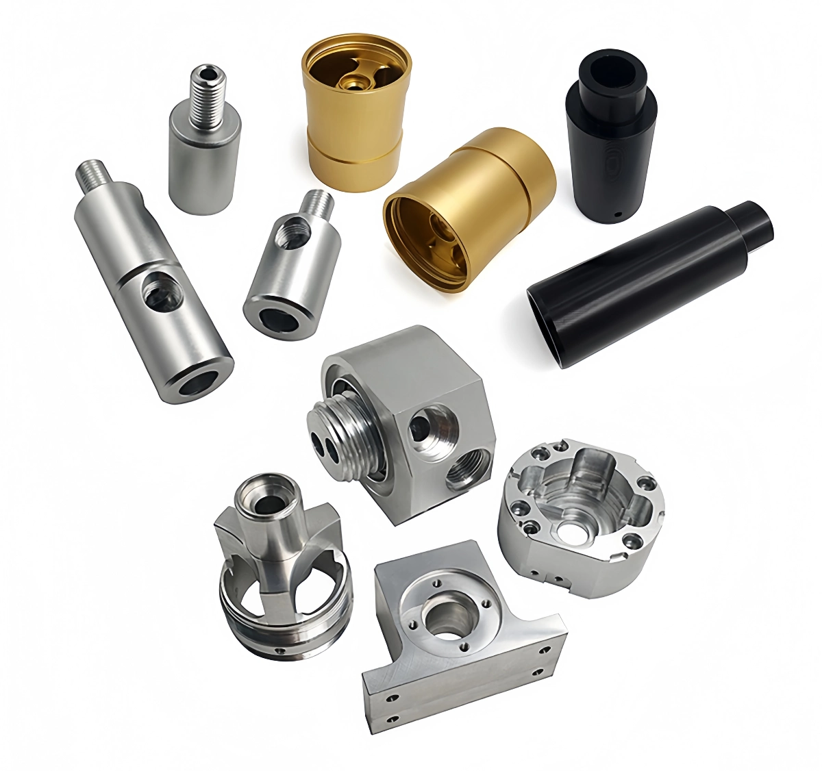
Modern CNC turning technology allows for the production of incredibly complex custom aluminum turned parts, often completing parts in a single setup that would have previously required multiple operations on different machines.
How is quality controlled for aluminum turned parts?
Precision is key for turned parts, but how do I know the parts I receive will actually meet the specs? What quality control steps should a good supplier follow?
As a quality-focused manufacturer, we control quality for aluminum turned parts through multiple stages: verifying raw material, in-process checks by operators using calibrated tools, first-article inspection, and final inspection, often using advanced CMMs for complex geometry.
Ensuring the quality of aluminum turned parts requires a systematic approach throughout the manufacturing process, from initial planning to final shipment. Relying solely on a final check is insufficient; quality must be built-in and verified at multiple points. A robust quality control (QC) plan is essential.
Key Stages of Quality Control:
Pre-Production:
Drawing and Specification Review: Carefully review the customer’s drawings and specifications to ensure all requirements (dimensions, tolerances, materials, finishes) are clearly understood and achievable. Any ambiguities are clarified before production starts. Design for Manufacturability (DFM) feedback may be provided.
Material Verification: Ensuring the correct aluminum alloy and temper is received from the supplier, often verified through material certifications (Mill Test Reports or MTRs). Material should be inspected for any visible defects.
Process Planning: Developing a detailed manufacturing plan, including selection of appropriate machines, tooling, workholding, and defining the sequence of operations and QC checkpoints. CAM programming includes verification steps.
In-Process Quality Control:
First Article Inspection (FAI): Thoroughly inspecting the first part produced in a run against all drawing specifications. This verifies that the machine setup, tooling, and program are correct before proceeding with the rest of the batch. FAI reports are often documented.
Operator Checks: Machinists perform regular checks of critical dimensions during the production run using calibrated hand tools like micrometers, calipers, depth gauges, thread gauges, and radius gauges. This helps catch any drift or issues (like tool wear) early. Frequency depends on tolerances and process stability.
Statistical Process Control (SPC): For higher volume runs, SPC techniques may be used to monitor key dimensions statistically, ensuring the process remains within control limits.
Tool Monitoring: Tracking tool wear and implementing scheduled tool changes to prevent degradation of part quality or dimensions.
Post-Production / Final Inspection:
100% or Sampling Inspection: Depending on the part’s criticality and customer requirements, either every part (100%) or a statistically valid sample (e.g., following AQL standards) undergoes final inspection.
Dimensional Verification: Checking all specified dimensions and tolerances using appropriate calibrated instruments. For complex geometries or very tight tolerances, a Coordinate Measuring Machine (CMM) is often essential. CMMs use a probe to touch multiple points on the part and compare the measured geometry against the CAD model.
Surface Finish Measurement: Using a profilometer or comparison gauges to verify surface roughness (Ra) requirements are met.
Visual Inspection: Checking for burrs, scratches, cosmetic defects, or any signs of improper machining.
Documentation: Recording inspection results and preparing final inspection reports if required by the customer. ISO 9001 certified shops typically have well-documented procedures for all QC steps.
Common QC Tools and Their Uses:
Tool
Typical Use in Turning QC
Precision Level
Digital Caliper
Measuring ODs, IDs, lengths, step heights
Moderate (~+/- 0.001″)
Micrometer (OD/ID/Depth)
Precisely measuring specific diameters or depths
High (~+/- 0.0001″)
Bore Gauge
Measuring internal diameters accurately
High
Thread Gauge (Go/No-Go)
Verifying thread pitch diameter
Pass/Fail
Radius Gauge
Checking fillet or corner radii
Moderate
Profilometer
Measuring surface roughness (Ra)
High (Quantitative)
Optical Comparator
Magnifying profile features for visual check/measurement
Moderate to High
CMM
Measuring complex 3D geometry, positions, form tolerances
Very High
A comprehensive quality control system, integrating checks before, during, and after machining, is fundamental to reliably producing high-quality aluminum turned parts that meet customer specifications.
Conclusion
High-quality aluminum turned parts require precision in dimensions, finish, and features. Lathes create these parts by rotating stock against cutting tools, with CNC enabling complexity through multi-axis control. Quality control involves checks throughout the process, ensuring reliable components for various industries.